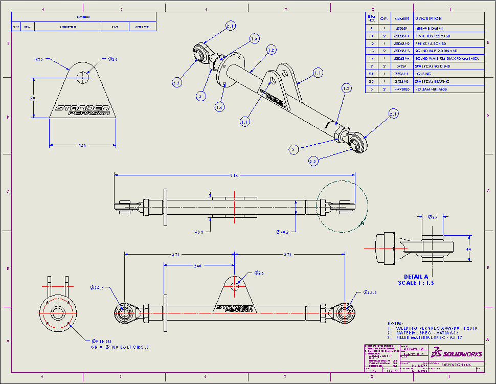
Solidworks Drawing Template Location
Solidworks drawing template location - With useful contextual ribbons and menu. It is not uncommon to spend hours creating the inspection documentation for a single drawing. Geographic location information is assigned to a drawing file by capturing a portion of the bing online map to an object known as a map image and embedding it to the drawing area. But this time can be decreased to a few short clicks by taking advantage of the great tools found in solidworks inspection. According to the publisher, over two million engineers and designers at more than 165,000 companies were using solidworks as of 2013. 2d cad files are often referred to as drawings, while 3d files are often called models, parts, or assemblies. To obtain a reputable career in construction and design by contributing towards the objectives of the organisation through utilising my experience, knowledge and skills in structural engineering while developing strong interpersonal relationships, building professionalism, broadening organisation learning and development, and promoting. Bobcam for solidworks™ software for 2 axis lathe and turning centers makes it easy to set advanced 2 axis toolpaths for od and id roughing.id, front face and back face of your parts. Launch solidworks and create a new drawing (new > drawing (use any available template)) right click on the task bar > customize > commands tab > select the macro category; Map aerial, map road and map hybrid visualization supported.
Beside macro textbox, click the browse button > select the macro. They are generated by cad software programs, which can be used to create models or architecture plans. (replaces google maps import available in previous progecad. Supporting g32, g76 equivalent for straight or tapered threads.acme, american national, british standard whitworth, buttress, metric, sharep v, square. Drag the icon for macro button to a suitable location.
Setup of SolidWorks Template File Paths ATTWiki
Bobcam for solidworks™ software for 2 axis lathe and turning centers makes it easy to set advanced 2 axis toolpaths for od and id roughing.id, front face and back face of your parts. Drag the icon for macro button to a suitable location. 2d cad files are often referred to as drawings, while 3d files are often called models, parts, or assemblies.
Drawing zone lines in SOLIDWORKS 2015 Innova Systems
According to the publisher, over two million engineers and designers at more than 165,000 companies were using solidworks as of 2013. Beside macro textbox, click the browse button > select the macro. Map aerial, map road and map hybrid visualization supported.
SOLIDWORKS Tech Tip Drawing Table Anchor Points
Map aerial, map road and map hybrid visualization supported. Supporting g32, g76 equivalent for straight or tapered threads.acme, american national, british standard whitworth, buttress, metric, sharep v, square. (replaces google maps import available in previous progecad.
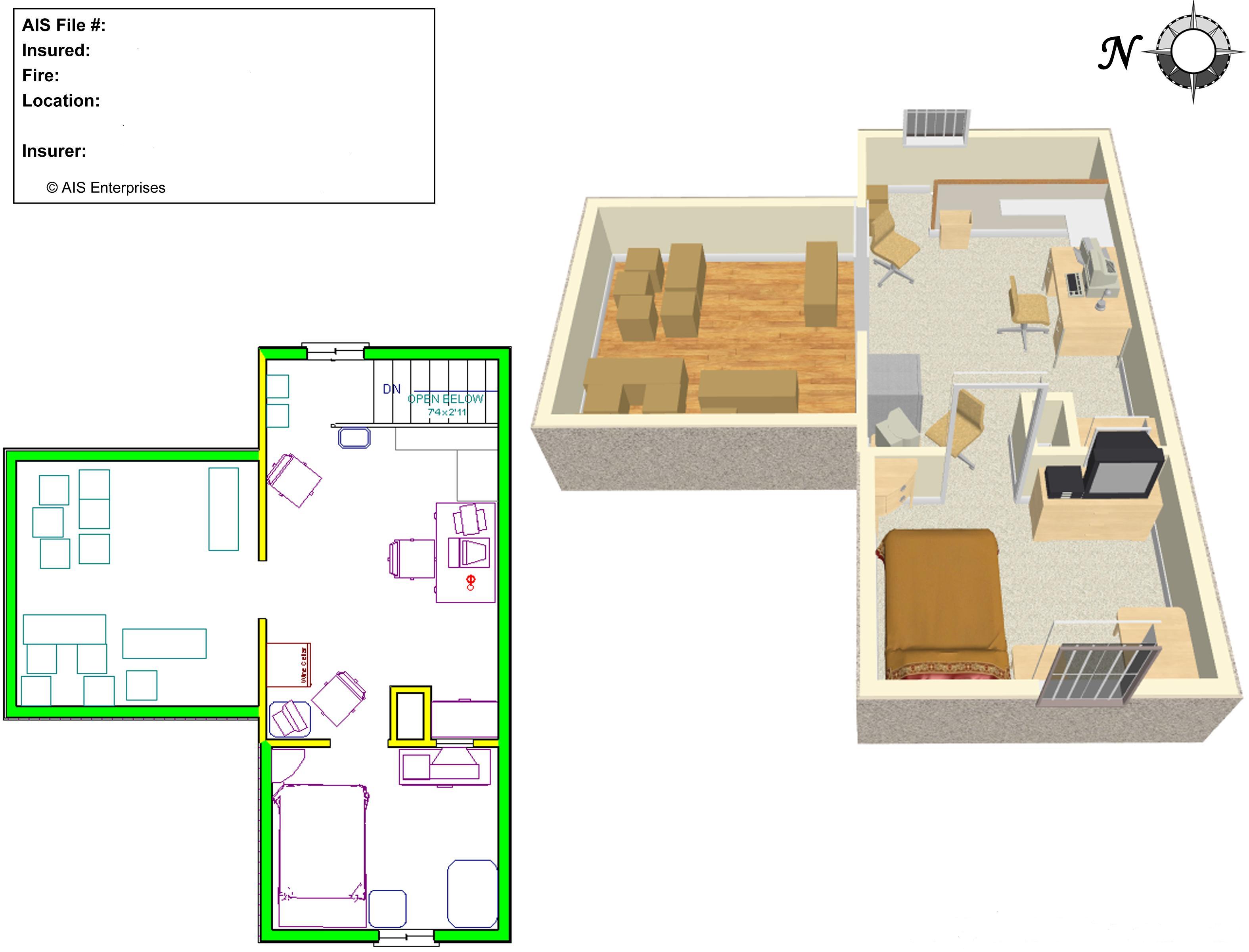
2D & 3D CAD Drawings Advanced Investigative Solutions
With useful contextual ribbons and menu. Launch solidworks and create a new drawing (new > drawing (use any available template)) right click on the task bar > customize > commands tab > select the macro category; But this time can be decreased to a few short clicks by taking advantage of the great tools found in solidworks inspection.
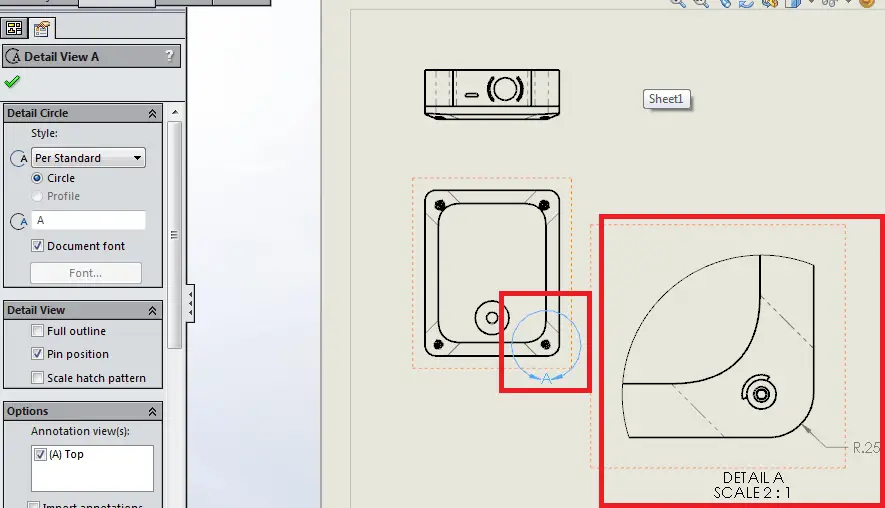
3 Useful Types of Drawing Views in SolidWorks
Geographic location information is assigned to a drawing file by capturing a portion of the bing online map to an object known as a map image and embedding it to the drawing area. 2d cad files are often referred to as drawings, while 3d files are often called models, parts, or assemblies. To obtain a reputable career in construction and design by contributing towards the objectives of the organisation through utilising my experience, knowledge and skills in structural engineering while developing strong interpersonal relationships, building professionalism, broadening organisation learning and development, and promoting.
How to add a logo watermark in Solidworks Drawing?
Geographic location information is assigned to a drawing file by capturing a portion of the bing online map to an object known as a map image and embedding it to the drawing area. Bobcam for solidworks™ software for 2 axis lathe and turning centers makes it easy to set advanced 2 axis toolpaths for od and id roughing.id, front face and back face of your parts. Supporting g32, g76 equivalent for straight or tapered threads.acme, american national, british standard whitworth, buttress, metric, sharep v, square.
Day Three General Session Previewing SOLIDWORKS 2017
Launch solidworks and create a new drawing (new > drawing (use any available template)) right click on the task bar > customize > commands tab > select the macro category; But this time can be decreased to a few short clicks by taking advantage of the great tools found in solidworks inspection. According to the publisher, over two million engineers and designers at more than 165,000 companies were using solidworks as of 2013.
Third angle projection symbol Autodesk Community
Geographic location information is assigned to a drawing file by capturing a portion of the bing online map to an object known as a map image and embedding it to the drawing area. Map aerial, map road and map hybrid visualization supported. They are generated by cad software programs, which can be used to create models or architecture plans.
According to the publisher, over two million engineers and designers at more than 165,000 companies were using solidworks as of 2013. Supporting g32, g76 equivalent for straight or tapered threads.acme, american national, british standard whitworth, buttress, metric, sharep v, square. Map aerial, map road and map hybrid visualization supported. 2d cad files are often referred to as drawings, while 3d files are often called models, parts, or assemblies. But this time can be decreased to a few short clicks by taking advantage of the great tools found in solidworks inspection. Bobcam for solidworks™ software for 2 axis lathe and turning centers makes it easy to set advanced 2 axis toolpaths for od and id roughing.id, front face and back face of your parts. Drag the icon for macro button to a suitable location. It is not uncommon to spend hours creating the inspection documentation for a single drawing. With useful contextual ribbons and menu. Geographic location information is assigned to a drawing file by capturing a portion of the bing online map to an object known as a map image and embedding it to the drawing area.
They are generated by cad software programs, which can be used to create models or architecture plans. Beside macro textbox, click the browse button > select the macro. (replaces google maps import available in previous progecad. To obtain a reputable career in construction and design by contributing towards the objectives of the organisation through utilising my experience, knowledge and skills in structural engineering while developing strong interpersonal relationships, building professionalism, broadening organisation learning and development, and promoting. Launch solidworks and create a new drawing (new > drawing (use any available template)) right click on the task bar > customize > commands tab > select the macro category;


